The article describes a very simple
homemade emergency light circuit that
can be used during power failures and
outdoors where any other source of
power might be unavailable.
The circuit uses LEDs instead of
incandescent lamp, thus making the unit
very power efficient and brighter with its
light output. Moreover, the circuit
employs a very innovative concept
especially devised by me which further
enhances the economical feature of the
unit.
Let’s learn the concept and the circuit
more closely:
The concept:
We know that LEDs require a certain
fixed forward voltage drop to become
illuminated and it is at this rating when
the LED is at it’s best, that is voltages
which is around its forward voltage drop
facilitates the device to operate in the
most efficient way.
As this voltage is increased, the LED
starts drawing more current, rather
dissipating extra current by getting
heated up itself and also through the
resistor which also gets heated up in the
process of limiting the extra current.
If we could maintain a voltage around
an LED near to its rated forward voltage,
we could use it more efficiently. That’s
exactly what I have tried to fix in the
circuit.
Since the battery used here is a 6 volt
battery, means this source is a bit
higher than the forward voltage of the
LEDs used here, which amounts to 3.5
volts. The extra 2.5 volts rise can cause
considerable dissipation and loss of
power through heat generation.
Therefore I employed a few diodes in
series with the supply and made sure
that initially when the battery is fully
charged; three diodes are effectively
switched so as to drop the excess 2.5
volts across the white LEDs (because
each diode drop 0.6 volts across itself).
Now as the voltage of the battery drops,
the diodes series are reduced to two and
subsequently to one making sure only
the desired amount of voltage reaches
the LED bank.
In this way the proposed simple
emergency lamp circuit is made highly
efficient with its current consumption,
and it provides backup for a much
longer period of time than what it would
do with ordinary connections.
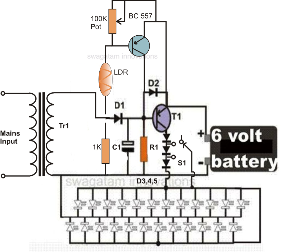
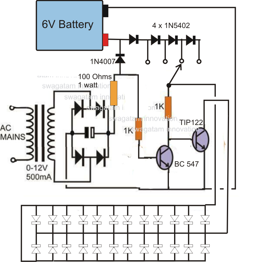
Efficient, Automatic, White LED
Emergency Light Circuit Description:
Referring the shown simple LED
emergency light circuit, we see that the
circuit is actually very easy to
understand, let’s evaluate it with the
following points:
The transformer, bridge and the
capacitor forms a standard Power
supply for the circuit. The circuit is
basically made up of a single PNP
transistor, which is used as a switch
here.
We know that PNP devices are
referenced to positive potentials and it
acts like ground to them. So connecting
a positive supply to the base of a PNP
device would mean grounding of its
base. Here, as long as mains power is
ON, the positive from the supply reaches
the base of the transistor, keeping it
switched off. Therefore the voltage from
the battery is not able to reach the LED
bank, keeping it switched off.
In the meantime the battery is charged
by the power supply voltage and it’s
charged through the system of trickle
charging.
However, as soon as the mains power
disrupts, the positive at the base of the
transistor disappears and it gets
forward biased through the 10K resistor.
The transistor switches ON, instantly
illuminating the LEDs.
Initially all the diodes are included in the
voltage path, and are gradually
bypassed one by one as the LED gets
dimmer.
HAVE ANY DOUBTS? FEEL FREE TO
COMMENT AND INTERACT.
Parts List for the proposed LED
emergency light circuit
R1 = 10K,
C1 = 100uF/25V,
D1, D2 = 1N4007,
D3---D6 = 1N5408,
T1 = BD140
Tr1 = 0-9V, 500mA,
LEDs = white, hi-efficiency, 5mm,
S1 = switch with three changeover
contacts.
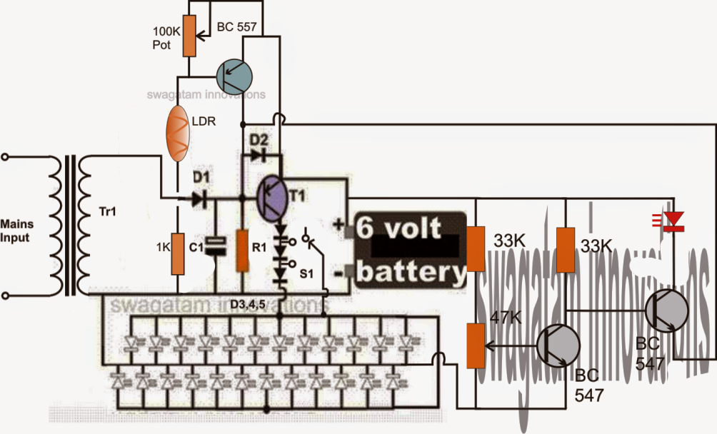
In response to the suggestion of one of
our avid readers, the above automatic
LED emergency light circuit has been
modified and improved with a second
transistor stage incorporating an LDR
trigger system. The stage renders the
emergency light action ineffective during
day time when ample ambient light is
available, thus saving precious battery
power by
avoiding unnecessary switching of the
unit.
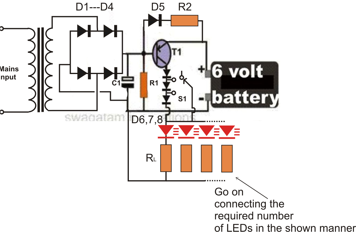
Circuit modifications for operating 150
LEDs, requested by SATY:
Parts List for the modified emergency
light circuit
R1 = 220 Ohms, 1/2 watt
R2 = 100Ohms, 2 watts,
RL = All 22 Ohms, 1/4 watt,
C1 = 100uF/25V,
D1,2,3,4,6,7,8 = 1N5408,
D5 = 1N4007
T1 = AD149, TIP127, TIP2955, TIP32 or
similar,
Transformer = 0-6V, 500mA
The following circuit shows how a low
voltage cut off circuit can be included in
the above design for preventing the
battery from getting over discharged.
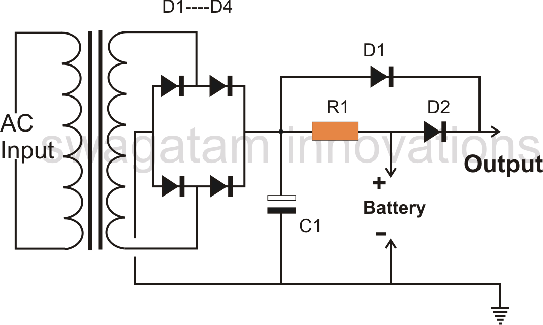
Power Supply Circuit with Emergency
Backup
The circuit shown below was requested
by one of the readers, it is a power
supply circuit which trickle charges
a battery when AC mains is available,
and also feeds the output with the
required DC power via D1. Now, the
moment AC mains fails, the battery
instantly backs up and the compensates
the output failure with its power via D2.
When input Mains is present, the
rectified DC passes through R1 and
charges the battery with the desired
output current, also, D1 transfers the
transformer DC to the output
for keeping the load switched on
simultaneously.
D2 remains reverse biased and is not
able to conduct because of higher
positive potential produced at the
cathode of D1.
However when mains AC fails, the
cathode potential of D1 becomes lower
and therefore D2 starts conducting and
provides the battery DC back up
instantly to the load without any
interruptions.
Parts List for an emergency light back
up circuit
All Diodes = 1N5402 for battery up to 20
AH, 1N4007, two in parallel for 10-20
AH battery, and 1N4007 for below 10
AH.
R1 = volt/charging current (Ohms)
Transformer Current/Charging current =
1/10 * batt AH
C1 = 100uF/25
Using NPN transistors
The first circuit can be also built using
NPN transistors, as shown here: