MAKE SIMPLE FM TRANSMITTER USING TWO 2N2222 TRANSISTORS
MAKE SIMPLE FM TRANSMITTER USING TWO 2N2222 TRANSISTORS
This circuit is pretty simple and I have
made it for number of times for myself
as well as for my friends to get them
good marks in lab practicals. :)
So the thing is, this circuit works like
charm!
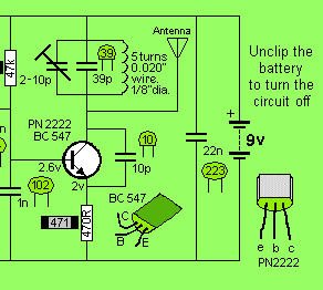
Things you need are given in circuit
diagram shown below. I have used two
2n2222 transistors and they work great,
you may try BC547 if you have got any.
Some discussion about working:
Circuit is comprised of two parts:
-Preamplifier
-Oscillator
Preamplifier Part
This parts follows simple theory which
goes like this: MIC grabs sound signals
from external environment, and 2n2222
which is biased in collector-feedback
method(also my favorite biasing
method) works as preamplifier for
incoming MIC signals.
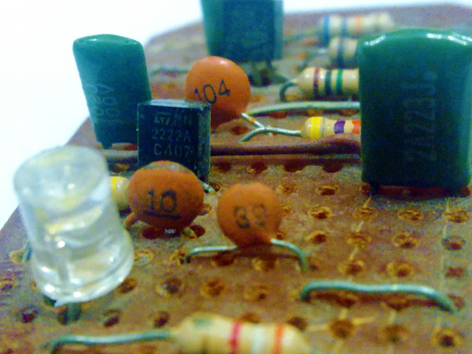
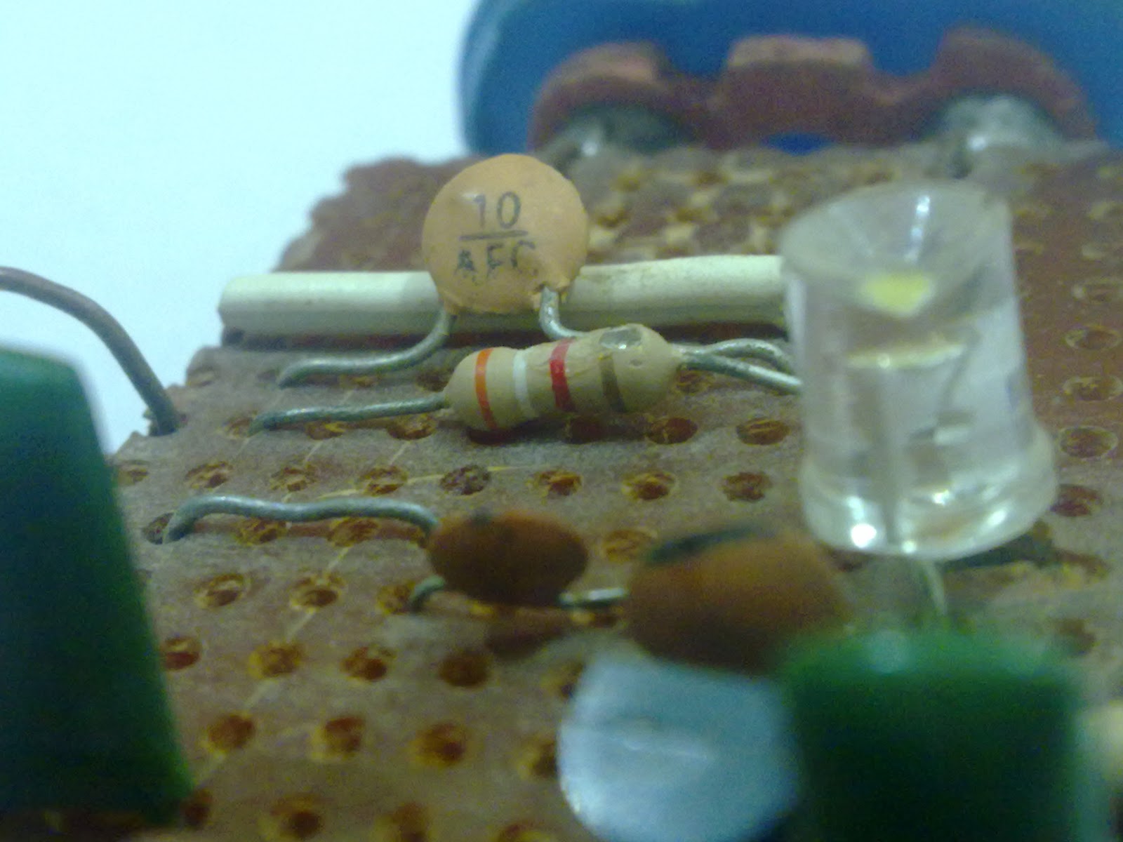
At collector of first 2n2222 transistor,
100nF capacitor (104) provides us
usable sound signals in electrical
format.
Oscillator Part
Forget LED, that is just a power
indicator!
The oscillator used in this circuit uses
no famous oscillator types like Colpitts
or Hartley oscillator but it uses its own
simple technique.
We know that a transistor can be turned
on by two methods:
1) By making base voltage positive
while holding emitter terminal a
constant voltage level.
2) By making emitter more negative by
holding base at constant voltage level.
This circuit uses later technique. Its
base is held rigid through 1nF capacitor
and emitter is brought to negative level
through 10pF capacitor (connecting
emitter and collector). It is kind of
feedback capacitor too. It provides LC
tank circuit a charging energy at proper
intervals which is very important for any
oscillator circuit.
Important:
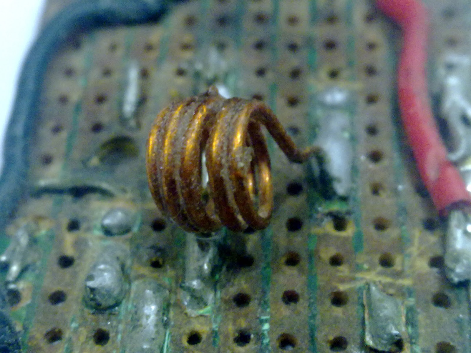
The inductor shown here is attached
right below the 39pF capacitor.
This was done in order to minimize
distance between LC tank components
i.e inductor and capacitor for stable
operation.(Also if you gotta try lot of
other inductors, then connecting a
inductor right on soldering points saves
lot of mess.)
I have not used VARIABLE CAPACITOR
as shown in circuit because it was not
available. Instead i tried varying inductor
spacing and my luck! i clutched desired
frequency. If variable capacitor is not
available to you too then you can use a
estimated constant capacitor value of
10pF (or others in range 2-10pF) in
parallel with 39pF that would make 49pF
in case you do not find right frequency
by varying inductor spacing.
You can see that i have glued the
inductor for sake of stability in
frequency but to my bad. this did not fix
problem. Every new day when i switched
this circuit on, tuning frequency was
little deviated,
HIDDEN FM JAMMER INSIDE A FM
TRANSMITTER
THIS IS FM JAMMER CIRCUIT YOU
ALWAYS KEEP SEARCHING FOR!
Think of basic theory, what is a fm
jammer? Some device that peels out all
sound from fm signal making all
receivers go dumb!
How this is actually and simply done?
Make a transmitter that emits a void
frequency without any sound signal or
modulation signal!
The circuit shown above is just
oscillator part of fm transmitter. It has
no information signal on it hence
whenever some radio receive is it, it
simply gets silent!.. So try it, you would
not be disappointed.
Make sure to tune this circuit to same
frequency as that you want to jam. like
Fm105 transmitting at 105MHz can be
jammed if this circuit oscillates at
105MHz.
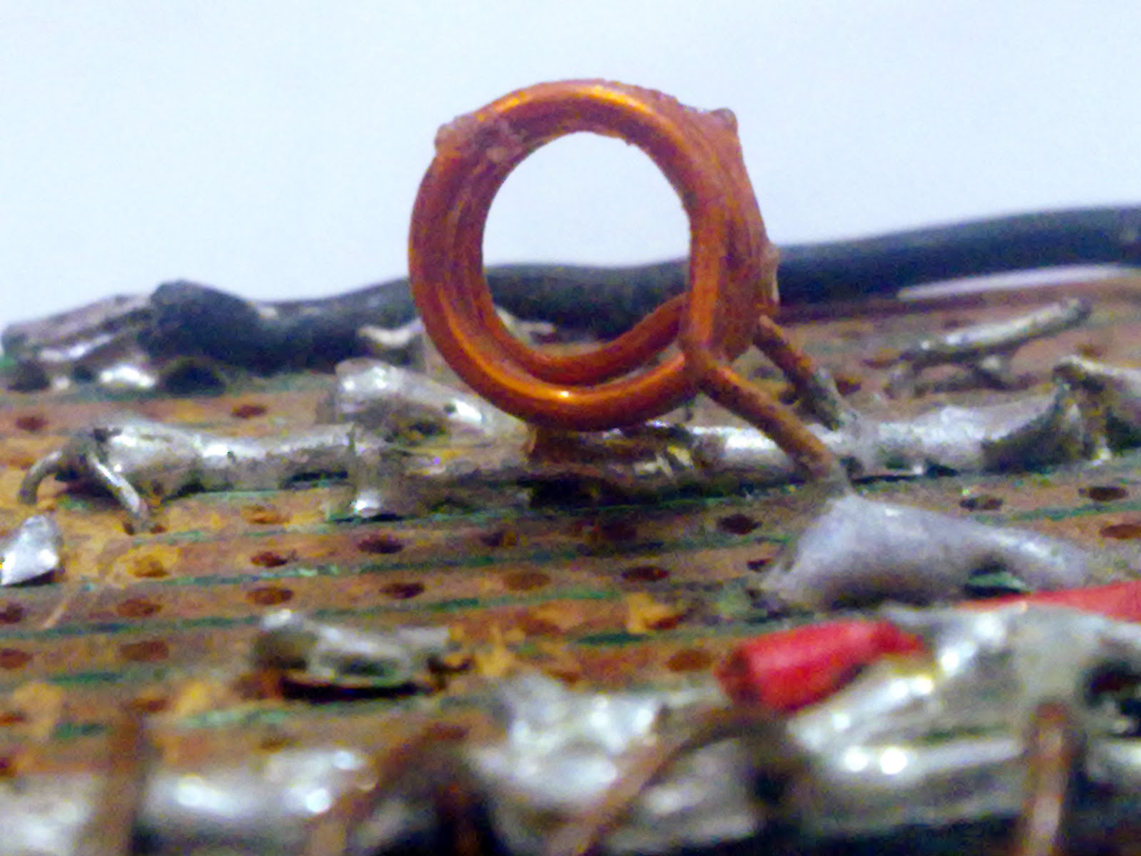
HOW TO MAKE INDUCTOR BY
YOURSELF?
Rule : Do not quit!
Making a inductor by yourself can be lot
fussy, when you have no measuring
instrument!
But quitting on making inductor does
not solve problem so you have to do it.
You must have alleast two dimension
parameters of inductor, its diameter and
number of turns.
One used here has dia=1/8 inch or
3.175 mm (say 4mm, though it can
greatly change value but you can
compensate it through varying spacing
between turns) and five turns.
If you have nothing cylindrical having
diameter of 4mm, try using small
capacitors like of 1uF or 3.3uF
(electrolyte) and make coil using them.
Use wire of standard gauge,can be
found in transformers secondary
winding.
FINAL CHECK
To check whether oscillator works or not
use this simple and elegant tool i have
made: View my next post.


12v battery diye led light jalate koto resistor lagbe..&auto charger kibe banabo...
use 330 ohms resistor. For auto charger view my post