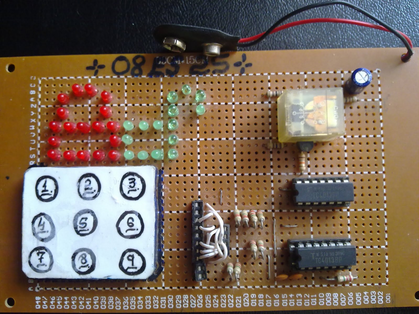
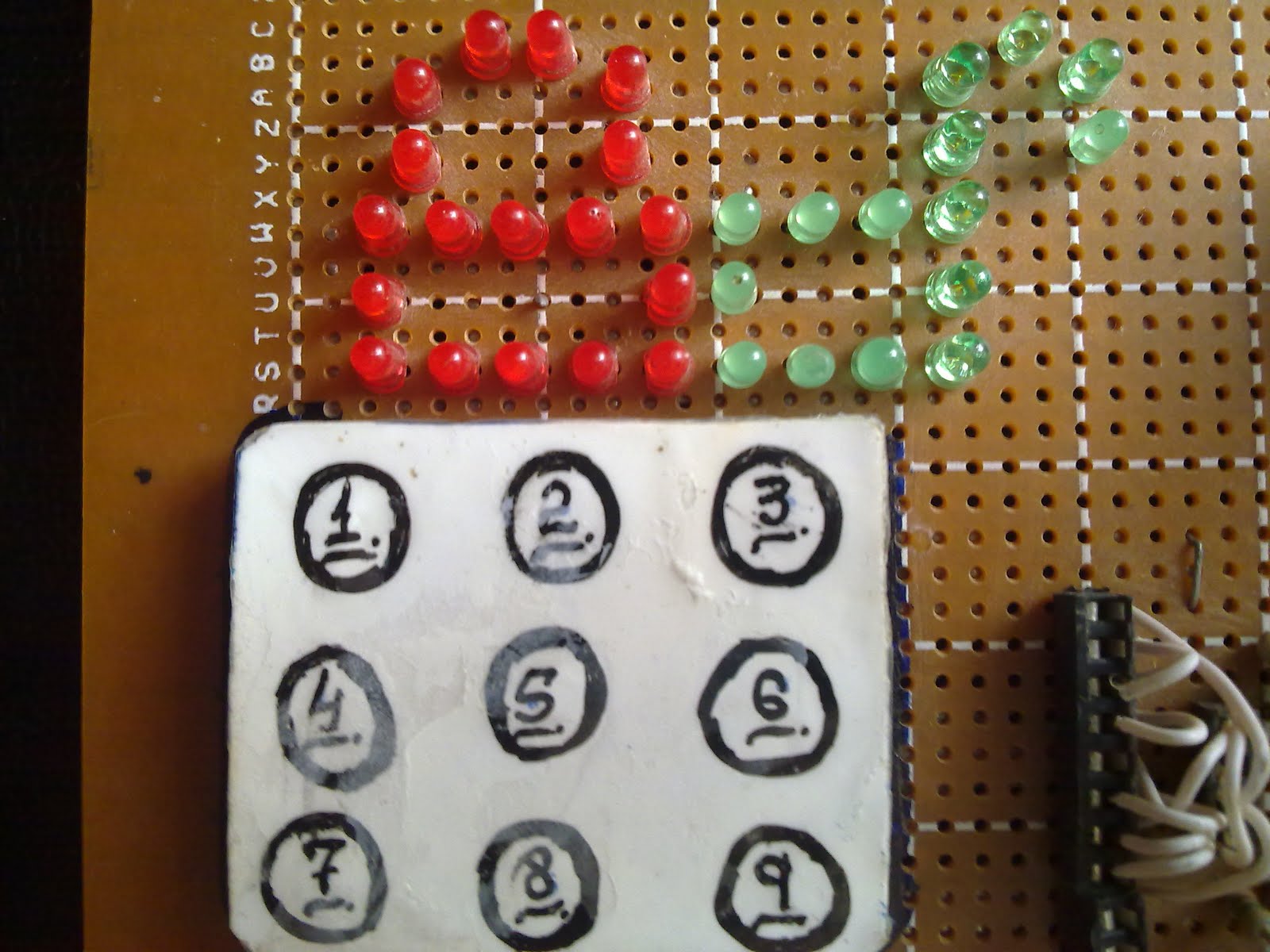
Today i am going to post simple project
viz "Electronic Combinational Lock"
made for subject of Sequential Circuit
Design. Here is a snapshot:
Need for the circuit:
The circuit is good start for reader's of
sequentail logic. It will greatly help you
to practically understand working of
flipflops, how they store data when
edge-triggered or set ,reset themselves
and how to take advantage of such
simple behaviour.
I am not talking about application of
this cricuit from security point of view
because for this circuit to protect
something , its has to be well protected
first. :0
BUT if its guaranteed that none can
touch internals of circuit , its damn
difficult to break code of system!
Peeping Inside:
The circuit is comprised of two D-flipflop
ICs. Each of this IC contains two D-ffs
hence circuit uses all four flipflops.
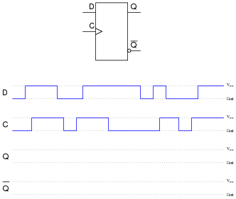
Working of circuit is pretty simple. Just
have look at blockdiagram of D-flipflop:
it has just one data pin, one clock pin,
one output and one inverted output.
Some facts:
-Given ffs will set/reset themselves at
high going pulse at set/reset pin
moreover on positive going pulse data
on Data-pin will be imported.
-In this lock circuit all four ffs(flipflops)
are connected in series.
-Circuit has 4-digit code i-e all four
clock lines of all four ffs.
Working procedure:
-Lets begin with input of first ff that is
connected to ground(pin5,IC1).
-As clock line of 1st ff will be driven
high through keypad, its outout will be
low since its input is connected to gnd.
-Input of 2nd ff(pin9,IC1) is connected
to o/p of 1st(pin1, IC1).
-Consequently when clock line of second
ff will be driven high,it will fetch data
from output of 1st ff hence its i/p ll also
be low.
-likewise press third and fourth digit to
make clock line of 3rd and 4rth ff high
to turn their o/p low .
- Now when keys are pressed in right
order begining from first to fourth ff, o/p
of fourth ff will be low.
-This low o/p will drive the base on
pnp-transistor(a pnp transistor requires
ground connection at base to turn itself
on).
-Transistor operates a relay which
drives any load connected.
Good Thing:
What i like about this circuit is that it
gives no chance to operator to make
mistake. If single digit goes wrong
whole code vanishes .Yeah you will have
to enter correct code form start.
How This Happens:
This is very simple indeed! All keys,
except those that you have dedicated for
code, are connected to set pin of D-ffs
(6,8 pins of both ffs). That is when you
press them, whole circuit gets set which
is actually reset condition for circuit .
Wait wait what am i talking??
Yes its like that, as i already described
that relay is driven by pnp transistor
which needs low signal for activation,
when set pin is made high, output of ffs
becomes high, which turns transistor off
that means things are secure.
About Keyboard:
The suspense about keyboard ends with
the thing that it contains micro-switches
beneath digits which i wrote through
pointer on thick paper then put a
transparent sheet to cover it up.
And ofcourse its my design :)
One pin of each switch is tied to VCC
and other is made avaible for usage.
A Little Change:
On the right of keyboard you can see
something like jumper connections.
This change is made to make circuit
flexible when a change in code is
needed.
I did not want to stay on same"built in"
code hence with this i can change code
of circuit any time i want.